Fog
A real-time fluid simulation is executed by evolving a two-dimensional flow's velocity and substrate properties over time. These properties are described by data sourced from interactive objects within the scene. The results of the fluid simulation are interpreted as a heightmap and subsequent gradient calculations are performed to derive a normal map. These maps are used to modify basis geometry stored in a graphics buffer and then rendered in a final additive pass to ensure that lighting is consistent with the scene's opaque geometry.
Sunset Surf

A sphere, illuminated by an orbiting light source, is rendered into a luminance mask and sampled by strips of particles in screen-space. The luminance value of each particle controls the weight of the line strips across their length. The motion of the lines is primarily influenced by an alternating Perlin noise velocity field. A collection of post processing effects is applied to distort the final image.
Hyperbolic Geometry

This visualization explores an icosahedron’s isomorphism between two metric spaces by embedding a hyperbolic space, defined within a spherical volume, inside a larger Euclidean space. The embedded sphere is animated such that its position and volume changes over time. Within this sphere, the Euclidean line segments are reinterpreted to ensure each line's hyperbolic counterpart forms an arc that is orthogonal to the sphere's surface. This configuration is achieved by maintaining the hyperbolic line segments on a plane defined by the line's endpoints and the sphere's center. By rotating this plane to align with the two-dimensional Poincaré disk model, the three-dimensional vector space simplifies into two dimensions. This transformation employs Duttra’s method of point inversion, constructing arcs orthogonal to the circle, passing through each hyperbolic line’s endpoints, effectively illustrating the unique relationship between hyperbolic and Euclidean geometries.
Seascape

Tessendorf's method of wave simulation is used to produce a three-dimensional tileable displacement map in real time. This displacement map, along with a divergence map, are then input to Unity’s VFX Graph, where they are used to modify the position, width, and other physical properties of a series of segments.
Geodesic
A collection of interlocking tetrahedrons is aligned on the surface of a sphere to construct a geodesic icosahedron. The geometry of individual tetrahedron is distorted and blended towards spherical geometry as it approaches an animated point in space. This configuration is rendered to a luminance mask and composited with a subtly animated full-screen gradient.
Vortex

A fluid simulation is used to render an elevation map and binned at regular intervals to produce contour lines. These contour lines are then projected at periodic angular divisions onto the internal surface of a rotating cylinder.
halftone
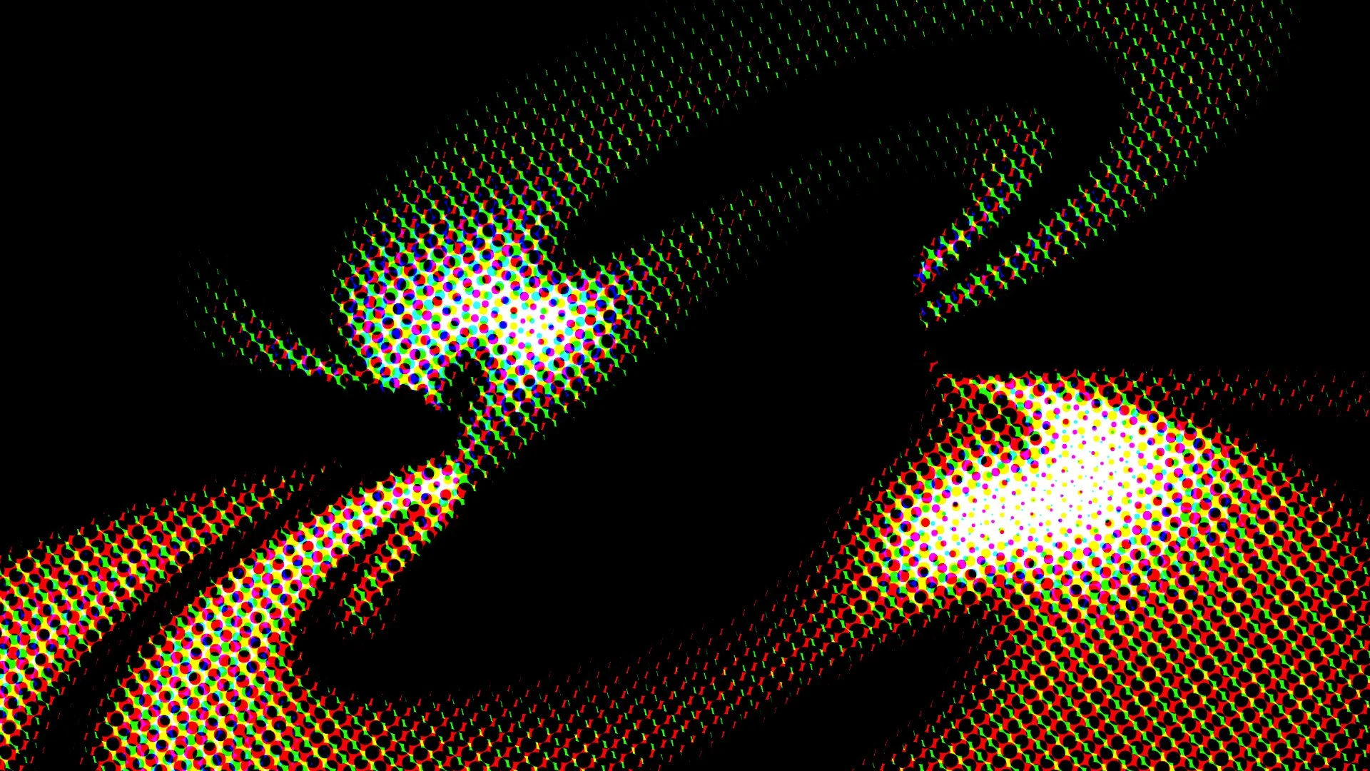
Three-dimensional animated toroidal geometry is rendered to a color buffer and separated into CMYK components. A particle simulation samples this buffer and transforms coordinates of each separate channel to specific screen angles. Individual dot position and radii are adjusted proportionally to the value at the projected position within the source buffer.
Strands

A large number of dynamic strands are simulated using Unity's Entity Component System. The strands, instantiated on the surfaces of various meshes, can form any geometric configuration. Each strand is modeled as a collection of damped springs with an additional restorative force and length constraint. A variable wind force, modulated over each strand by sampling a periodic volumetric noise function, is applied globally. Coulomb forces are exerted between strands and the lights. The physics of individual strand components are updated using the Verlet Integration method. Strands are modeled as a series of capped cylinders, organized into a 3D hashmap for efficient collision detection, with collisions treated as perfectly elastic to maintain energy conservation. The results from the physics simulation are transformed into a series of connected Bezier curves, producing the final smooth lines.
orbit

Spherical geometry is displaced by a two-dimensional advection simulation. The final output of the simulation is exported as maps of concentration, velocity, pressure, and gradients. The simulation is driven by per-frame injections of velocity and concentration from several VFX graphs, which write to specific simulation maps. These VFX graphs adhere to the sphere’s surface yet are transformed in vertex shaders by the inverse of the spherical projection to minimize distortion when the textures are sampled by their coordinates. The advection simulation’s textures are processed by a compute shader to produce geometry with smoothed normals and tangents, which are calculated from a scaled gradient map of concentration interpreted as height.
advection

A time-dependent vector field of velocities is continuously updated through Jacobi iteration on the two-dimensional Poisson pressure equation. Alongside, a scalar field carrying color data is transported by the evolving velocity field. To restore vorticity details lost due to dissipation, the curl of the velocity field is employed. These fields are generated on the GPU using a compute shader and then fed into a particle simulation. Several million particles evolve within the domain by sampling the velocity field, managed within Unity's VFX Graph.
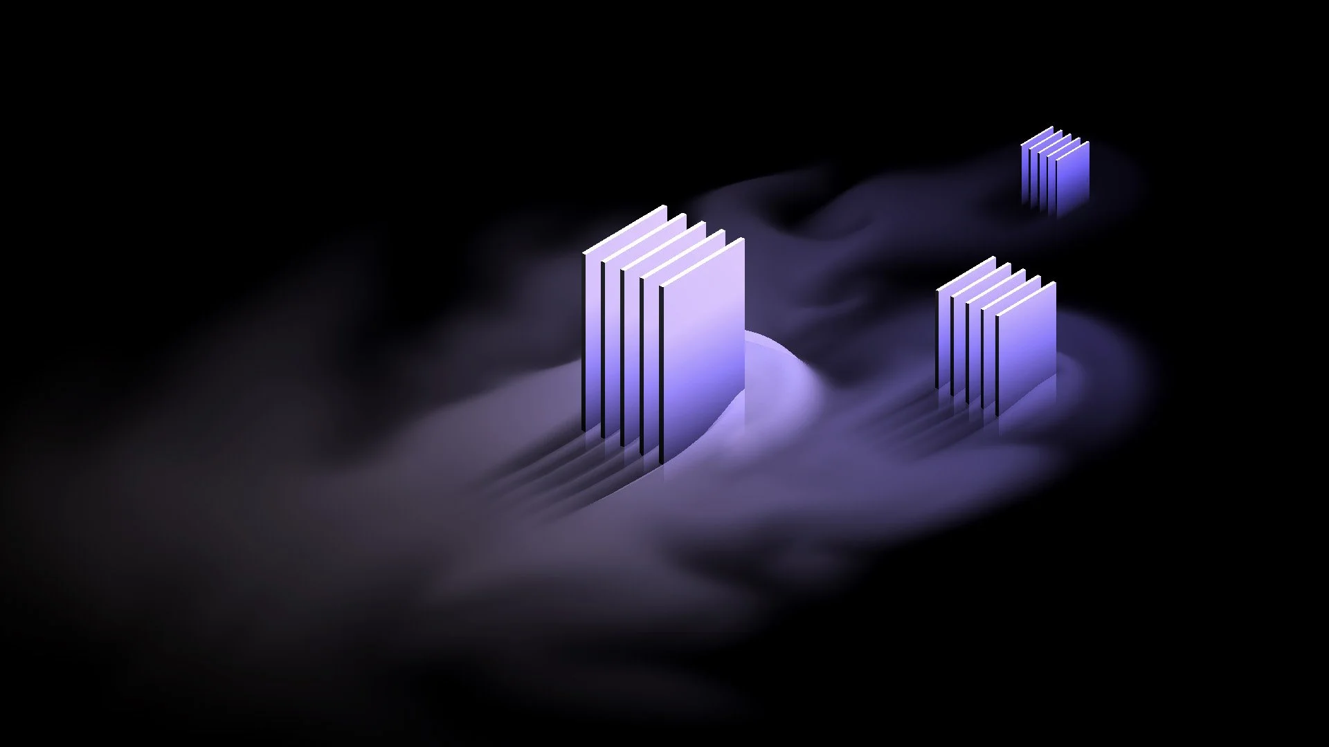
Slices

An array of depth slices is generated from a volume. At each slice depth, an orthographic frustum is created with clipping planes aligned to the plane defining that slice depth. Each slice depth is rendered in two passes to determine the intersection of geometry within the volume at that specific depth. In the first pass, meshes are drawn into the depth buffer with culling disabled. The second pass involves drawing back-face fragments with depth values equal to those in the depth buffer. This approach allows back-face fragments to be visible through any gaps in the geometry, indicating they are interior to the volume. This method is effective for an arbitrary number of watertight meshes contained within the volume.
Dispersion

Ray tracing is used to sample surface data at the intersections of two meshes in real-time. This data is collected in an array of buffers, which are then consumed by Unity's VFX Graph. The arrays are sampled by particles upon their spawn, allowing them to mirror the properties of the surface at their respective spawn locations. To visualize the particle effect, Unity's Universal Render Pipeline is employed.
WAVES

Compute shaders calculate displacement and normal maps for low to medium frequency waves using the inverse fast Fourier transform, following Tessendorf's method. A crease map is generated by evaluating the Jacobian of each texel, which the surface shader uses to highlight breaking wave fronts. High frequency noise is introduced by blending pre-computed normal maps onto the final surface. The source mesh is relatively low resolution, containing only several thousand vertices, which necessitates the application of distance-based tessellation to enhance detail in the final mesh. Subsurface scattering is simulated by increasing emission proportionally with the vertical displacement, modified by the normal and view direction.
Transmission
A DXR photon map pass embedded in Unity HDRP to achieve non-photorealistic rendering.
Fluid

A two-dimensional fluid simulation is executed in a compute shader and visualized on a plane that intersects a spherical spiral. The intersection is captured per frame and stored in a texture by analyzing the depth buffer. This texture then serves as the source material for the bulk of the simulation. Surface disturbances on the fluid are modeled using Unity's VFX Graph, which modifies the simulation's velocity field. Distortion effects on the spherical spiral are created by sampling an animated volumetric texture. Unity's Universal Render Pipeline is utilized to split rendering along the fluid's surface, isolating the distortion to the geometry below the surface.
Mirrors

Reflection hierarchies are constructed for each reflective surface and stored in command buffers. These buffers are drawn recursively by combining the individual command buffers of each distinct surface, which allows the reflection hierarchies to be traversed serially, reducing the need for multiple render textures. Each reflection depth requires only a single render texture and a corresponding reflection matrix. Reflective surfaces are further optimized by culling through scissor and backface testing at each recursive depth. Refraction effects on exterior surfaces are simulated by adjusting the final screen space position based on the fragment's projected normal direction.
The soft body physics simulation is implemented using Unity's Entity Component System. A tetrahedral mesh acts as a damped mass-spring system, utilizing an iterative integration method. Restitution forces are applied during collisions to maintain the physical integrity of interactions. The resultant surface from the soft body simulation is then converted into a mesh and rendered with real-time reflections provided by a cubemap.
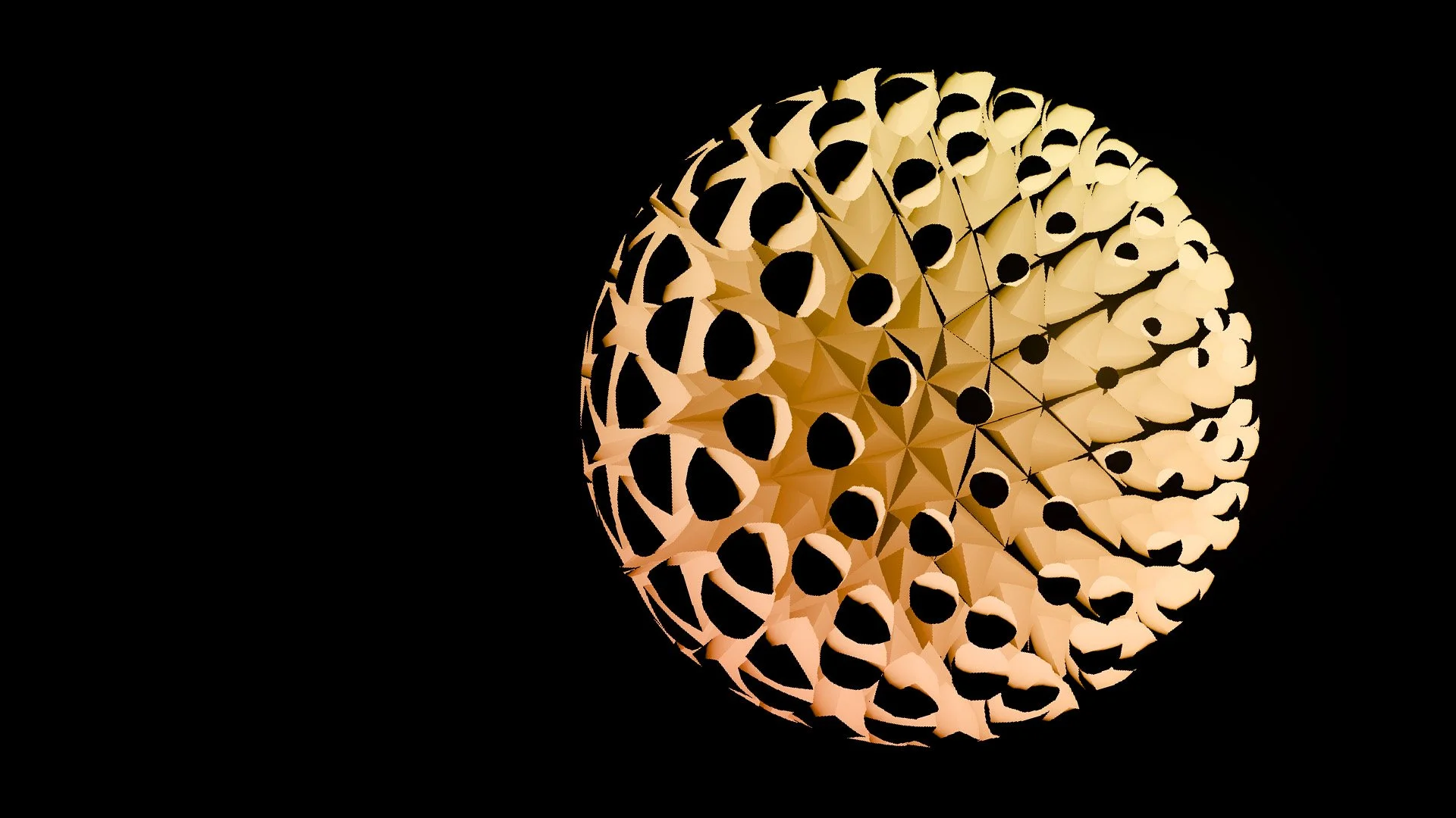
Photon Mapping

A photon map is generated by tracing the primary refractions of photons emitted from a point source as they pass through ball lenses, with each sphere's aperture calculated to cull photons that require excessive refraction/reflection steps to exit. This careful calibration, combined with a photon distribution function and precise sampling resolution, allows for meticulous control over the density of incident photons along the spherical surfaces. The accumulated photon map is then projected onto a plane and integrated into texture space for future use. Unity's High Definition Render Pipeline (HDRP) has been modified to blend this photon map with the screenspace normal buffer directly into the diffuse light layer of the G-buffer, effectively simulating light transmission through the spheres. Prior to the final rendering output, a custom tilt-shift blur is applied to enhance focus and depth in the visual presentation.
Differential Line Growth

A differential line growth algorithm is implemented using Unity's Entity Component System, where the line is dynamically subdivided at arbitrary segments each frame to facilitate its extension. Throughout the simulation, each segment of the line undergoes harmonic oscillation, experiences a relaxation force, and interacts with collision forces to model complex behaviors and interactions. For efficient collision detection, segments are organized within a spatial hashmap. To refine the visual output, the line is subsequently down-sampled and smoothed using a weighted centroid method. The simulation is conducted in local space with the final segment positions being transformed to world space. This transformation leverages a precomputed position map, enabling the differential line growth to adapt to various surface geometries without the need for an analytical surface description, thus enhancing the flexibility and applicability of the simulation across different modeling scenarios.